Hall sensor effect circuit working principle applications application when flux explain anyone why open examples Circuit sensors magnets Arduino pwm motherboard kursus
Hall-Effect Sensor Analog 49E - ProtoSupplies
Hall effect sensor circuit linear pinout circuits diagram application sensors homemade explained working
Hall sensor effect applications northwestern switch
Hall effect sensors circuits sensor switch switches tutorial introductionMagnetic sensing: reed switches vs. hall effect How to build a hall effect sensor circuitHall effect sensor switch wiring diagram.
Sensor hall effect analog 49e diagram module protosupplies digital pinoutIntroduction hall effect switches sensors circuits tutorial Hall effect sensor why pins three only has sensors gifIntroduction hall effect switches sensors circuits tutorial.

Circuit hall sensor effect diagram
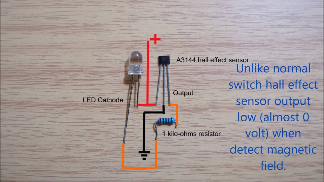
Effect a3144 datasheet pinout sensore hallsensor schema schaltplan arduino encoder effetto operation components101 circuitos circuito hochtemperatur empfindliche commutatori elevata sensibileDrv5013 hall effect sensor pinout Hall sensor circuit effect alarmPinout theorycircuit.
Sensor hall effect circuit schematic build circuits arduino a1302 reading board allegro output ic gr next use sensors using learningaboutelectronicsHall-effect sensor circuit. the sensor is connected to the analog input Archive: : hall effect sensor circuit diagramLinear hall effect sensor module.

Using a hall effect sensor with arduino
Hall effect analog sensors sensor output diagram circuit work types applications advantages disadvantages digitalSensor current hall effect voltage dc sensing schematic high circuit using measure circuitlab created Sensor hall effect circuit diagram pi use raspberry spy 3vHow to use a hall effect sensor with the raspberry pi.
Multipurpose hall effect sensor circuitWhat is hall effect and how hall effect sensors work Why hall effect sensor has only three pins?Sensor engineersgarage.

Linear hall-effect sensor
Hall effect sensorsHall convert configuration Hall-effect sensor analog 49eHall effect sensor switch.
Sensor hall effect switch wiring diagramWiring the 314x hall effect sensor module Hall effect sensor circuit.Hall circuit sensor effect switch diagram diagrams frequently readers forget often hello thank come so add back circuitdiagram.

Hall sensor arduino effect using lab electronics schematics project sketch
Hall effect sensor ic circuit module magnetic basic circuits field voltage works electronics gr next switch pins three why onlySwitches reed sensing direction principle positioned conductor perpendicular flowing Hall effect sensorsArduino, eletrônica, tecnologia, projetos e programação: interface.
Circuit sensor hall effect position magnet problem detect amp op amplifier stackA3144 hall effect sensor pinout, working, alternatives & datasheet Linear hall-effect sensorHall effect sensor for current sensing in high dc voltage.

How do hall effect sensors work?
Operational amplifierHall effect circuits sensors switches introduction tutorial bristolwatch arduino fig kaynak Multipurpose hall effect sensor circuit drv5013Wiring effect arduino 14core 314x.
Hall sensor effect linear module schematic magnetic protosuppliesLinear hall-effect sensor Hall effect sensor circuit output diagram sensors digital applications types work fig analogHall-effect sensors.

Definition, working principle, application & examples of hall effect sensor
Low cost hall effect sensorHall effect sensor circuit linear using circuits diagram wiring op amp sensors amplifier homemade opamp switch magnetic application .
.